
This post is also available on my colleague’s blog.
Abstract
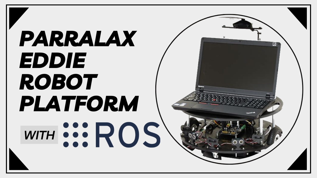
In this article, we provide a comprehensive report on how to get started with the Parallax Eddie robot platform with ROS2, and we discuss the problems we encountered during our study.
The package is available here.
Setting up the Kinect
In this section, we will begin by explaining how to utilize the Kinect sensor in ROS2. To start, you need to install the kinect_ros2 package, which offers RGB-D topics for ROS2. This package requires the installation of libfreenect, which is a userspace driver specifically designed for the Microsoft Kinect sensor.
Problems
If you carefully adhere to the instructions provided in the kinect_ros2 readme and ensure that all dependencies of libfreenect are satisfied, you should not encounter any issues. You can build libfreenect by following the given set of instructions.
1
2
3
4
5
6
7
8
git clone https://github.com/OpenKinect/libfreenect
cd libfreenect
mkdir build && cd build
cmake .. -DBUILD_OPENNI2_DRIVER=ON\
        -DBUILD_EXAMPLES=ON\
        -DBUILD_PYTHON3=OFF\
make
sudo make install
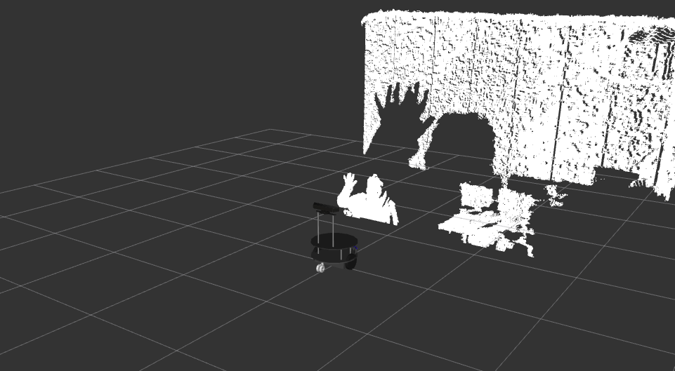
Once you have installed libfreenect successfully, the building process of kinect_ros2 should be smooth and error-free. It will publish several topics, including image_raw, camera_info, depth/image_raw, and depth/camera_info. The outputs of the image_raw and depth/image_raw topics can be observed in Figure 1 using rviz2.
1
ros2 run kinect_ros2 kinect_ros2_node
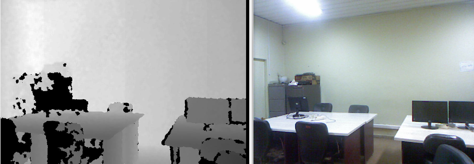 The result of the image_raw and depth/image_raw topics shown in rviz2.
Add timestamp to RGB images
After analyzing the topics in the kinect_ros2 package, it was observed that the RGB topics were missing timestamps. Timestamps are essential for synchronizing data from various sensors and components in a robotic system. They ensure accurate correlation and fusion of data captured or processed by different modules.
\noindent To address this issue, the timer callback in the kinect_ros2_component.cpp file has been modified to include timestamps for RGB images. This modification ensures that each RGB image is assigned a timestamp, enabling proper synchronization and temporal integration of the data within the robotic system.
1
2
3
4
5
6
7
8
9
10
11
12
13
14
15
16
17
18
19
20
21
22
23
24
25
26
void KinectRosComponent::timer_callback()
{
  freenect_process_events(fn_ctx_);
  auto header = std_msgs::msg::Header();

  auto stamp = now();
  header.stamp = stamp;
  depth_info_.header.stamp = stamp;
  rgb_info_.header.stamp = stamp;

  if (_depth_flag) {
    header.frame_id = "kinect_depth";
    auto msg = cv_bridge::CvImage(header, "16UC1", _depth_image).toImageMsg();
    depth_pub_.publish(*msg, depth_info_);

    _depth_flag = false;
  }

  if (_rgb_flag) {
    header.frame_id = "kinect_rgb";
    auto msg = cv_bridge::CvImage(header, "rgb8", _rgb_image).toImageMsg();
    rgb_pub_.publish(*msg, rgb_info_);

    _rgb_flag = false;
  }
}
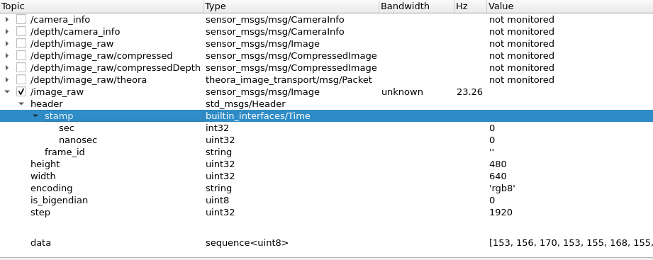
 image_raw topic before and after of setting the timestamps.
Bringup the Robot
To proceed further, the subsequent action involves initiating the robot. Initially, retrieve the most recent iteration of the eddiebot-ros repository and ensure that all the required elements are installed by executing the provided commands below.
1
2
rosdep update
rosdep install -i from-path src --rosdistro humble -y
Then connect the USB port of the robot and grant permission to it.
1
sudo chmod a+rw /dev/ttyUSB0
eddiebot-bringup package
This package facilitates the conversion of higher-level instructions, provided via ROS2 topics, into lower-level instructions specifically designed for the eddiebot. The file eddie_controller.cpp subscribes to the eddie/simple_velocity topic, which contains both the linear and angular velocity information for the robot. Given that the eddiebot operates as a differential-drive system, it necessitates separate linear and angular velocities for each of its wheels. Therefore, the approach outlined in section 6 is implemented to generate distinct velocities for each wheel.
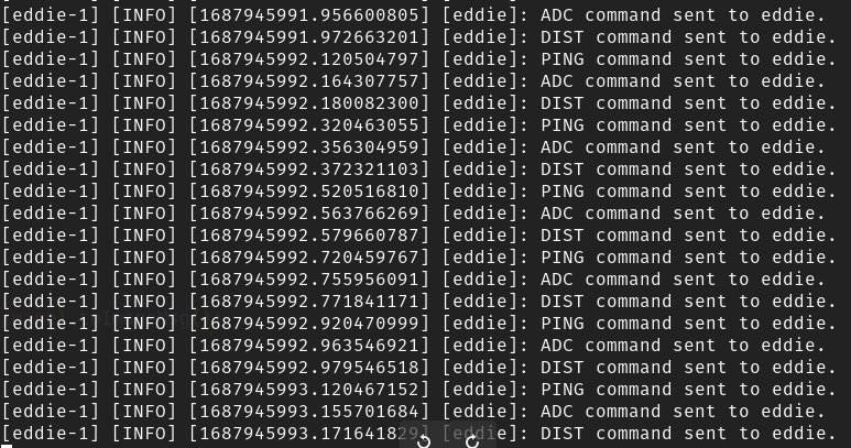 The desired output of the eddiebot-bringup.
Subsequently, using ROS2 services, these higher-level instructions are transmitted to their corresponding services defined in “eddie.cpp,” enabling the creation of low-level instructions. These instructions are then sent to the eddiebot via a serialized connection.
This package can be executed using the launch file as follows:
1
ros2 launch eddiebot_bringup eddie.launch.yaml
eddiebot-nav package
This package incorporates essential transformations, remappings, and modifications within its launch files to enable various localization and mapping functionalities. The primary launch file, “eddiebot.launch.py,” must be executed subsequent to the completion of the eddiebot-bringup process.
1
ros2 launch eddiebot_nav eddiebot.launch.py
After completing the preceding steps, the eddiebot is prepared for movement, and navigation topics are being published to facilitate its operation. To verify the functionality of these topics, you can launch the “view_model” launch file from the eddiebot-rviz package. By moving the robot, the model representation should correspondingly move as well (ensure that the “fixed_frame” is set to “odom”).
The pointcloud_to_laserscan package is employed to generate synthetic LaserScans. The point clouds are published on the “/points” topic, which can be visualized by adding the topic to RViz2 and configuring its Quality of Service (QoS) to “BestEffort”. The simulated LaserScans, on the other hand, are published on the “/scan” topic. By analyzing the /scan topic, we can find the range and FOV which is described in the videos.
teleop-twist-keyboard
The subsequent step involves installing teleop-twist-keyboard, which provides a means to generate twist messages using the keyboard and publish them on a specific topic. Then, the eddiebot_vel_controller package converts these twist messages into SimpleVelocity messages, a prerequisite for the eddiebot-bringup package.
A potential issue may arise due to the absence of the catkin_pkg package, which can be resolved by installing it using the provided command below:
1
sudo pip install -U catkin_pkg
Once the teleop_twist_keyboard package has been built successfully, you can execute it using the following code snippet:
1
ros2 run teleop_twist_keyboard teleop_twist_keyboard --ros-args -r /cmd_vel:=/eddie/cmd_vel
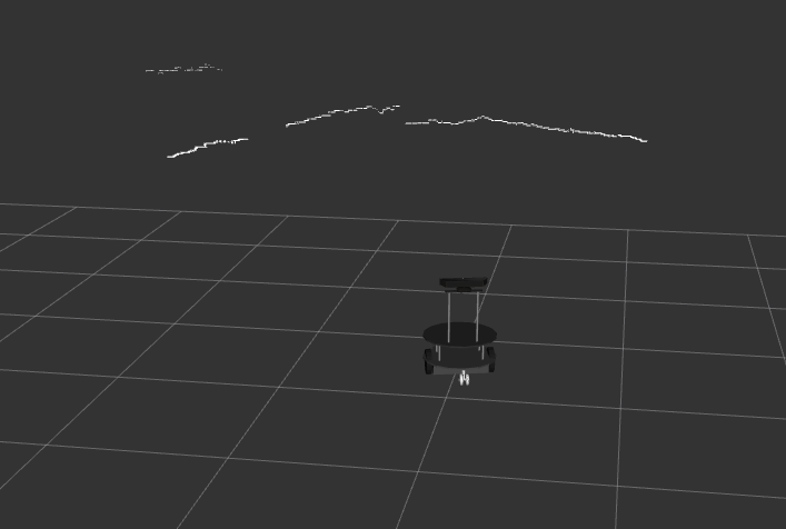 /points and /scan topics shown in RViz2.
Networking
Once you have connected both machines to the same network, such as a mobile hotspot, it is important to disable any VPN or proxies that might interfere with the connection. To ensure network availability, make sure that the ROS_LOCALHOST_ONLY parameter is set to zero and both machines have the same ROS_DOMAIN_ID.
1
2
export ROS_LOCALHOST_ONLY=0
export ROS_DOMAIN_ID=0
After completing these steps, you should verify if both machines have the same IP range by running the following command:
1
hostname -I
If all the necessary steps have been followed and the IP ranges are correct, you can proceed to run a simple talker and listener using the demo_nodes_cpp package. The talker will publish a simple “Hello, world!” message, and the listener should receive and display it.
Once you have confirmed that the talker and listener are functioning properly, you can proceed to bring up the robot and launch the main navigation launch file on the main laptop. Ensure that all the necessary components and dependencies are properly set up for the robot.
On the teleop laptop, you can check the topics being published by the main laptop. Use the appropriate commands or tools to view the topics and their data. This will allow you to monitor the robot’s navigation and observe the relevant topics from the teleop laptop.
2D SLAM
In the current setup, the SLAM_Toolbox is utilized for mapping using the simulated LaserScans, while Nav2 is employed for navigation based on the created map. It is crucial to adjust the parameters of each package, as defined in the configs folder of the eddiebot-nav package, to ensure optimal performance.
For the SLAM_Toolbox, one key component to consider is the range of the kinect sensor. Real LaserScans typically cover a larger and wider area, whereas the fake LaserScans are generated from a kinect depth sensor with a limited range. A suitable range for the kinect in this case could be 5 meters.
Regarding Nav2, an important parameter to tune is the frequency at which it publishes velocity commands to the robot. The default value specified in the velocity_smoother is 20 Hz, which can be quite high. If the robot is not moving despite receiving instructions, it could be due to the excessively high publish rate. By reducing this value to 0.2 (indicating that the velocity is published every 5 seconds), Nav2 can effectively control the robot’s movement.
Additional key values to consider in Nav2 are the minimum and maximum velocities and accelerations, which should be adjusted based on the specific requirements of the robot and its environment.
One potential issue to address is the discrepancy in topic names between the eddiebot-vel-controller package and Nav2. Currently, the package publishes on “/eddie/cmd_vel,” while Nav2 publishes on “/cmd_vel” without any remapping. To resolve this, either the eddiebot-vel-controller package should publish on “/cmd_vel” or Nav2 needs to be remapped to publish on “/eddie/cmd_vel.” This adjustment will ensure proper communication between the packages. The commands of this part are as follows: (each on a separate terminal)
SLAM
1
2
3
4
  ros2 launch eddiebot_bringup eddie.launch.yaml
  ros2 launch eddiebot_nav eddiebot.launch.py
  ros2 launch eddiebot_rviz view_robot.launch.py
  ros2 launch eddiebot_nav slam.launch.py
Nav2
1
2
3
4
5
  ros2 launch eddiebot_bringup eddie.launch.yaml
  ros2 launch eddiebot_nav eddiebot.launch.py
  ros2 launch eddiebot_rviz view_robot.launch.py
  ros2 launch eddiebot_nav localization.launch.py world:="map.yaml"
  ros2 launch eddiebot_nav nav2.launch.py
Analyze Kinematics
Encoder reading model
To determine the speed and direction of travel, a pair of wheel encoders are used. They calculate the number of pulses detected from each wheel. Each wheel encoder consists of two sensors and can measure a distance resolution equal to 1/36th of the circumference of the robot’s wheel. According to the sensor, it generates 36 pulses for every full rotation of the wheel. Using this information, the distance covered within a single pulse duration is provided below.
\[d = \cfrac{2 \pi r}{36}\]Then the distance traveled by each wheel can be written as follows:
\[d_R = (s_{(R, t)} - s_{(R, t-1)}) \cdot d\] \[d_L = (s_{(L, t)} - s_{(L, t-1)}) \cdot d\]where $s_{i, t}$ is the encoder tick for wheel $i$ at time $t$.
Odometry model
By using the teleop_keyboard package, Twist messages are published. These messages are subsequently converted into Simple_Velocity messages by the eddiebot_vel_controller package, containing both the angular and linear velocities of the robot. Considering the usage of a differential drive robot, it becomes necessary to calculate the individual velocities for each wheel. This calculation is performed by the eddie_controller within the eddiebot_bringup package. The mathematical intuition underlying this process is as follows:
\[\omega_R = \cfrac{V + \omega \cdot b/2}{r}\] \[\omega_L = \cfrac{V - \omega \cdot b/2}{r}\]where $V$ and $\omega$ are the linear velocity and angular velocity of the robot, and $b$ is the wheel separation.
Since $\omega = \frac{V}{r}$, linear velocities can be derived as follows:
\[V_R = \omega \cdot (R + b/2)\] \[V_L = \omega \cdot (R - b/2)\]where $R = \frac{V}{\omega}$.
To convert velocity from meters per second to position per second, the velocities are divided by $d$.
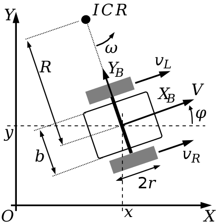 Differential Drive Kinematics.
The odometry model is used to describe the robot’s position and orientation as a function of the movement of its wheels using the information obtained by wheel encoders described in section 6.1. The movement direction is then calculated by the difference in velocities of its two wheels.
- If the linear velocities of the left wheel $V_L$ and the right wheel $V_R$ are the same, the robot travels in a straight line.
- When $V_L$ and $V_R$ have different values, the robot moves in the direction of the wheel with the lower linear velocity.
- When $V_L$ and $V_R$ have equal magnitudes but opposite directions, the robot rotates while staying stationary. If the left wheel is moving forward, the robot spins in a clockwise direction, and if the right wheel is moving forward, the robot spins counterclockwise.
Under the assumption that the wheels maintain contact with the ground at all times, without any slipping, they follow curved paths on the plane. These paths are designed in a manner that ensures the vehicle consistently rotates around a specific point known as the instantaneous center of rotation (ICR).
\[d = R \Delta \varphi\] \[d_r = (R + b/2) \Delta \varphi\] \[d_l = (R - b/2) \Delta \varphi\] \[\Delta \varphi = \cfrac{d_r - d_l}{b}\] \[d = \cfrac{d_r + d_l}{2}\]where $d_l$ and $d_r$ are the distances traveled by the left and right wheels. In general, $d_r$ and $d_l$ are calculated using the information gathered by wheel encoders, and formulas described in second and third formulas. Thus, the change in the orientation of the robot is calculated by the low-level information of the wheel encoders.
To calculate the current position, the next step involves finding the derivatives of the position. This can be achieved by determining the changes in the x and y directions using the following formulas:
\[\Delta x = d \cos(\varphi)\] \[\Delta y = d \sin(\varphi)\]Where $d$ is specified in equation(12). Thus, the new position can be calculated using the following update rule:
\[\hat{p} = \begin{bmatrix} x\\y\\\varphi \end{bmatrix} + \begin{bmatrix} \Delta x\\ \Delta y \\ \Delta \varphi \end{bmatrix}\]In the case of a differential drive system, the robot’s angular and linear velocities are provided, which are used to drive individual velocities for each wheel. The motion equations used to calculate these velocities are analogous to the equations mentioned earlier. Therefore, the motion equations can be written as follows:
\[\dot{\varphi} = \cfrac{r}{b} (v_r - v_l)\] \[v = \cfrac{(v_r + v_l)}{2}\] \[\dot{x} = v \cos(\varphi)\] \[\dot{y} = v \sin(\varphi)\]Visual SLAM
In this phase, we will be utilizing RTAB-Map, which is an RGB-D, Stereo, and Lidar Graph-Based SLAM approach. It incorporates an incremental appearance-based loop closure detector that utilizes a bag-of-words approach to determine the likelihood of a new image belonging to a previous location or a new location. When a loop closure hypothesis is accepted, a new constraint is added to the map’s graph, and a graph optimizer minimizes the errors within the map.
Similar to Section 5, in this part, we will begin by using the RTAB-Map SLAM method to create a map. The map generated by RTAB-Map will be saved in the .ros folder located at /home/user. To create a map using RTAB-Map, follow the commands provided below: (note that the default value of robot_description in eddiebot_rviz launch files are set to true)
1
2
3
4
ros2 launch eddiebot_bringup eddie.launch.yaml
ros2 launch eddiebot_nav eddiebot.launch.py
ros2 launch eddiebot_rviz view_robot.launch.py
ros2 launch eddiebot_nav rtabmap.launch.py
If the use_rtabmap_viz parameter is set to true in the RTAB-Map launch configuration, a separate window will appear displaying the visualization of the Kinect data and its corresponding feature points. This visualization is similar to the one shown in Figure 6 of the documentation. The window provides a visual representation of the captured data, allowing you to observe the features and details extracted from the Kinect sensor during the mapping process.
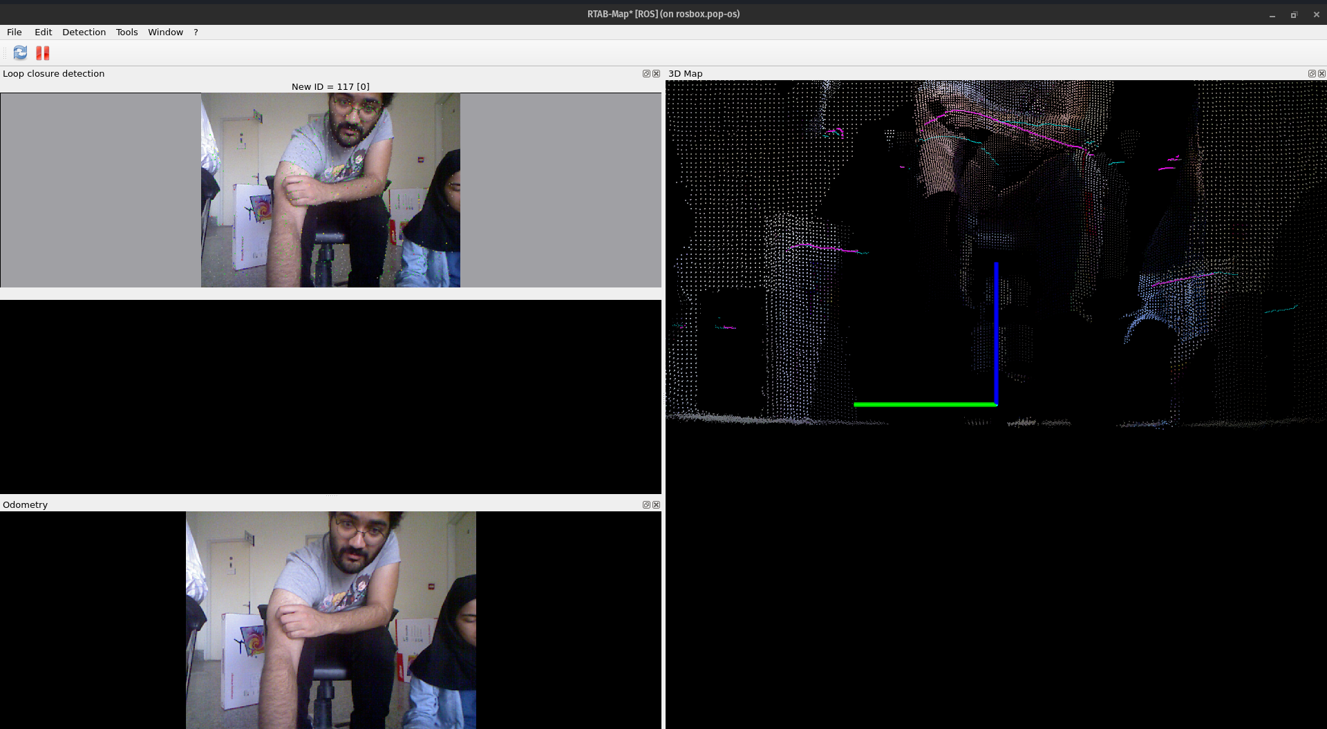 set use_rtabmap_viz true.
After creating the map using RTAB-Map, you can load it and proceed with navigation tasks similar to those described in Section 5. To accomplish this, run following commands in separate terminals:
1
2
3
4
5
ros2 launch eddiebot_bringup eddie.launch.yaml
ros2 launch eddiebot_nav eddiebot.launch.py
ros2 launch eddiebot_rviz view_robot.launch.py
ros2 launch eddiebot_nav rtabmap.launch.py localization:='true'
ros2 launch eddiebot_nav nav2.launch.py
Extra
A package is created to read IMU data using websockets from an Android device and publish it on the IMU topic. IMU messages consist of three main components: angular velocity, linear acceleration, and orientation. It’s important to note that the orientation of the Android sensor is given in Euler values, which need to be converted to Quaternion for the IMU message in ROS2. Once these conversions are done, the EKF config should be set up to subscribe to the IMU topic, and an EKF node can be used to fuse the IMU data with odometry by utilizing the published transforms.
The pdf of the report is also available: